
LiDAR Filters
Bandpass filters, windows and mirrors for 850 to 1,550 nm LiDAR and ToF receivers
 PB01 · IMAGE PENDINGNear-infrared bandpass filters and windows for LiDAR receivers
Receiver Filters, Windows and Mirrors for LiDAR and Time-of-Flight Sensors
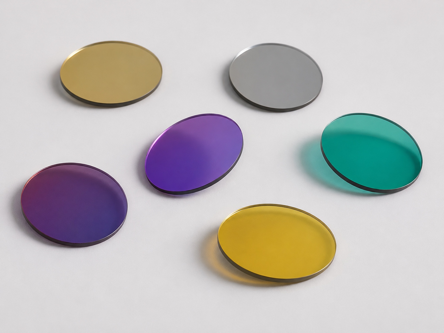
A LiDAR receiver must see its own laser return against sunlight. A bandpass filter in front of the detector passes the laser line and blocks the rest.
We make LiDAR filters at 850, 905, 940, 980, 1,064, 1,535 and 1,550 nm, from 4 to 60 nm wide, with transmission above 90%.
Blocking runs from OD2 to OD6, typically from 300 nm to 1,100 nm, or to 1,800–2,000 nm for 1,064 and 1,550 nm filters.
Many of our LiDAR filters are designed for 3° incidence. Thickness options run from 0.55 to 3.0 mm, with optional conductive coatings.
For automotive LiDAR, filters are qualified from −40 °C to +85 °C, with humidity resistance at 85 °C / 85% RH and salt-spray resistance to ASTM B117, for more than 10 years of service. Receiver filters reach more than 95% transmission, out-of-band blocking of OD6 and above, and transition widths under 1%.
We also make LiDAR windows and mirrors; see below. Specify a custom LiDAR filter
Choosing by Laser Wavelength
850 and 905 nm. Common for short- and mid-range LiDAR with edge-emitting lasers, where sunlight is strong. Use a filter that blocks the visible deeply and is wide enough for the laser’s drift; our 905 nm designs are 10, 30 or 50 nm wide.
940 nm. Used in short-range LiDAR, structured light and VCSEL-based ToF, where solar background is lower. Our 940 nm filters run from 26 nm wide at OD5 to 60 nm wide at OD3.
 D01 · IMAGE PENDINGSolar spectrum with common LiDAR laser wavelengths marked
1,535 and 1,550 nm. Eye-safe wavelengths that allow more laser power and longer range. Our 1,550 nm filters are 10 to 30 nm wide with OD4 to OD5 blocking out to 1,800–2,000 nm.
980 nm. A 60 nm wide 980 nm filter passes more than 98% for systems that need throughput more than deep blocking.
1,064 nm. Used in surveying, mapping and airborne LiDAR with high pulse energy, so coating durability matters. Our 1,064 nm filters run from 4 to 40 nm wide, most at OD5, many blocking out to 1,200 or 1,800 nm.
What Decides LiDAR Filter Performance
Signal-to-background. Sunlight covers the whole spectrum, so every nanometre of passband lets more in. The narrowest filter that still holds your laser line over temperature and angle gives the best signal-to-noise.
Blocking range. The filter must block everything your detector can see, not just the visible. Silicon detectors respond to about 1,100 nm; InGaAs detectors for 1,550 nm need blocking further out.
Angle. Many of our LiDAR filters are specified at 3 ± 2°, a small tilt often used to keep reflections off the optical axis. Mount them at that angle, or tell us your design angle.
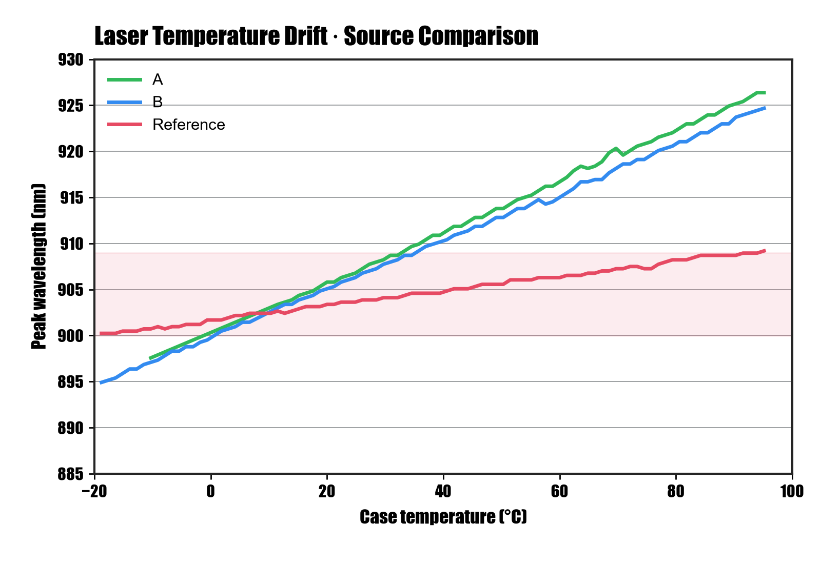 D03 · IMAGE PENDINGA 905 nm laser line shifting with temperature across 10, 30 and 50 nm passbands
Laser wavelength drift is compared with different receiver passband widths to show how temperature changes can reduce signal transmission.
How Wide Should the Filter Be?
The laser moves with temperature. Edge-emitting 905 nm lasers typically drift about 0.3 nm per °C; over an automotive range of −40 to +85 °C, that is around 35 nm. VCSELs at 940 nm drift about 0.07 nm per °C, around 9 nm. The filter itself moves far less, a few hundredths of a nanometre per °C.
The receiver’s field of view adds angle. Using the standard tilt formula, a 905 nm filter shifts about 3 to 6.5 nm at 10° and 7 to 14.5 nm at 15°, depending on its effective index. At the edge of a wide field, a 10 nm filter can miss the return.
Add the two, and you have the minimum passband. That is why 905 nm receivers often use 30 to 50 nm filters, while VCSEL-based 940 nm systems can go narrower. Angle shift in detail
Filters, Windows and Mirrors for LiDAR
Receiver Filters
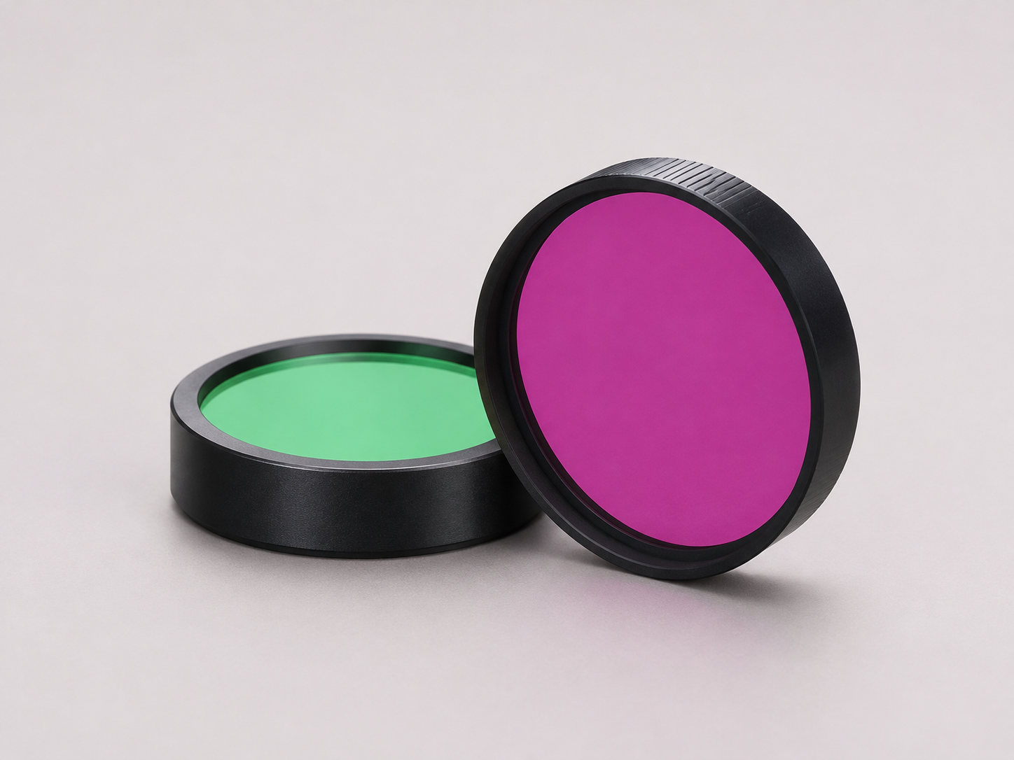
Bandpass filters at 850 to 1,550 nm, 4 to 60 nm wide, OD2 to OD6, 0.55 to 3.0 mm thick, with optional conductive coating. See the tables below.
LiDAR Windows
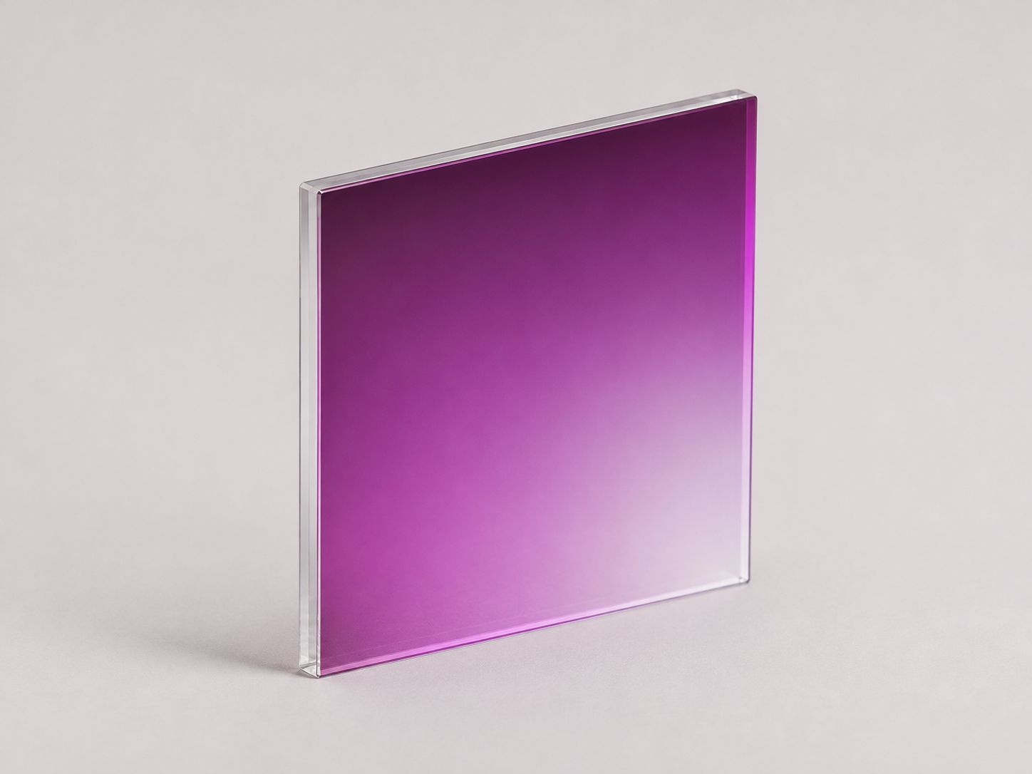
Cover windows that transmit 99% or more at 850, 905, 1,535 or 1,550 nm, ±15 nm, at 0°, with optional conductive coating. Learn more

LiDAR Mirrors
45° mirrors reflecting 99% or more at 800–900, 890–920, 900–980 or 1,500–1,600 nm for folding the laser and receiver paths. Learn more
Standard LiDAR Filters
| Model | CWL (nm) | FWHM (nm) | Avg. T | Blocking | Blocking range (nm) | AOI |
|---|---|---|---|---|---|---|
| BP940-26,OD5 | 940 ± 2 | 26 | > 95% | OD5 | 350–920 / 965–1,100 | 3 ± 2° |
| BPP940-60,OD3 | 940 ± 2 | 60 ± 2 | > 92% | OD3 | 350–900 / 978–1,100 | 3 ± 2° |
| BP980-60,OD2 | 980 ± 2 | 60 ± 1.5 | > 98% | OD2 | 300–932 / 1,025–1,150 | 3 ± 2° |
| BP1064-4nm,OD5 | 1,064 | 4 | > 90% | OD5 | 350–1,100 | 3 ± 2° |
| BP1064-6,OD4 | 1,064 ± 2 | 6 | > 90% | OD5 / OD4 | 200–1,058 / 1,070–1,800 | 3 ± 2° |
| BPF1064-10nm,OD5 | 1,064 ± 2 | 10 | > 92% | OD5 | 350–1,200 | 3 ± 2° |
| BPF1064-30nm,OD5 | 1,064 ± 2 | 30 ± 1 | > 92% | OD5 | 350–1,200 | 3 ± 2° |
| BPF1064-40nm,OD5 | 1,064 ± 2 | 40 ± 1.5 | > 93% | OD5 | 350–1,200 | 3 ± 2° |
| BP1064-40,OD6 | 1,064 ± 2 | 40 ± 2 | > 92% | OD6 | 200–950 | 0 ± 2° |
| BP1550-20,OD5 | 1,550 ± 2 | 20 ± 1.5 | > 92% | OD5 | 900–1,528 / 1,578–1,800 | 3 ± 2° |
More LiDAR Designs
| Design | CWL (nm) | FWHM (nm) | Peak T | Blocking | AOI |
|---|---|---|---|---|---|
| BP850/10 | 850 ± 2 | 10 ± 2 | ≥ 90% | OD ≥ 3 @ 300–1,100 nm | 0° |
| BP850/30 | 850 ± 3 | 30 ± 3 | ≥ 90% | OD ≥ 3 @ 300–1,100 nm | 0° |
| BP850/50 | 850 ± 5 | 50 ± 3 | ≥ 90% | OD ≥ 3 @ 300–1,100 nm | 0° |
| BP905/10 | 905 ± 2 | 10 ± 2 | ≥ 90% | OD ≥ 3 @ 300–1,100 nm | 0° |
| BP905/30 | 905 ± 3 | 30 ± 3 | ≥ 90% | OD ≥ 3 @ 300–1,100 nm | 0° |
| BP905/50 | 905 ± 5 | 50 ± 3 | ≥ 90% | OD ≥ 3 @ 300–1,100 nm | 0° |
| BP940/10 | 940 ± 2 | 10 ± 2 | ≥ 90% | OD ≥ 3 @ 300–1,100 nm | 0° |
| BP940/30 | 940 ± 3 | 30 ± 3 | ≥ 90% | OD ≥ 3 @ 300–1,100 nm | 0° |
| BP940/50 | 940 ± 5 | 50 ± 3 | ≥ 90% | OD ≥ 3 @ 300–1,100 nm | 0° |
| BP1550/10 | 1,550 ± 2 | 10 ± 2 | ≥ 90% | OD avg ≥ 4 @ 600–2,000 nm | 0° |
| BP1550/30 | 1,550 ± 3 | 30 ± 3 | ≥ 90% | OD avg ≥ 4 @ 200–1,700 nm | 0° |
Ask us for the curves and samples of any design in the second table.
More LiDAR Designs
| Design | CWL (nm) | FWHM (nm) | Peak T | Blocking | AOI |
|---|---|---|---|---|---|
| BP850/10 | 850 ± 2 | 10 ± 2 | ≥ 90% | OD ≥ 3 @ 300–1,100 nm | 0° |
| BP850/30 | 850 ± 3 | 30 ± 3 | ≥ 90% | OD ≥ 3 @ 300–1,100 nm | 0° |
| BP850/50 | 850 ± 5 | 50 ± 3 | ≥ 90% | OD ≥ 3 @ 300–1,100 nm | 0° |
| BP905/10 | 905 ± 2 | 10 ± 2 | ≥ 90% | OD ≥ 3 @ 300–1,100 nm | 0° |
| BP905/30 | 905 ± 3 | 30 ± 3 | ≥ 90% | OD ≥ 3 @ 300–1,100 nm | 0° |
| BP905/50 | 905 ± 5 | 50 ± 3 | ≥ 90% | OD ≥ 3 @ 300–1,100 nm | 0° |
| BP940/10 | 940 ± 2 | 10 ± 2 | ≥ 90% | OD ≥ 3 @ 300–1,100 nm | 0° |
| BP940/30 | 940 ± 3 | 30 ± 3 | ≥ 90% | OD ≥ 3 @ 300–1,100 nm | 0° |
| BP940/50 | 940 ± 5 | 50 ± 3 | ≥ 90% | OD ≥ 3 @ 300–1,100 nm | 0° |
| BP1550/10 | 1,550 ± 2 | 10 ± 2 | ≥ 90% | OD avg ≥ 4 @ 600–2,000 nm | 0° |
| BP1550/30 | 1,550 ± 3 | 30 ± 3 | ≥ 90% | OD avg ≥ 4 @ 200–1,700 nm | 0° |
Ask us for the curves and samples of any design in the second table.
What to Send Us
- Laser type and wavelength (edge-emitter, VCSEL, fiber)
- Operating temperature range
- Receiver field of view or cone angle
- Detector type (silicon, InGaAs, SPAD)
- Blocking needed and over what range
- Size, thickness and coating (AR, conductive)
- Annual volume
Developing a LiDAR or ToF sensor? Send us your laser, temperature range, field of view and detector, and we will recommend a passband, blocking level and angle, and quote samples. Contact us