
Beamsplitters
Pick a standard filter below, or send us your wavelength for a custom design.
Plate Beamsplitters That Split by Ratio or by Wavelength
When one beam has to feed two places, such as a camera and a detector, or a signal and a reference, a beamsplitter divides it: part is transmitted, part reflected, in a fixed ratio or by wavelength.
We make ratio beamsplitters from 50:50 to 90:10 at 45° across 400 to 700 nm, with each channel held to ±5 percentage points.
For wider ranges there is a broadband splitter that transmits 80% on average from 550 to 1,100 nm.
To split by wavelength, we can separate two near-infrared lines only 25 nm apart, such as 1,540 and 1,565 nm.
Beyond plate beamsplitters, cube beamsplitters made of two cemented right-angle prisms give no beam shift and equal path lengths. Polarizing and non-polarizing versions, custom R/T ratios and coatings for high-power laser beams are available.
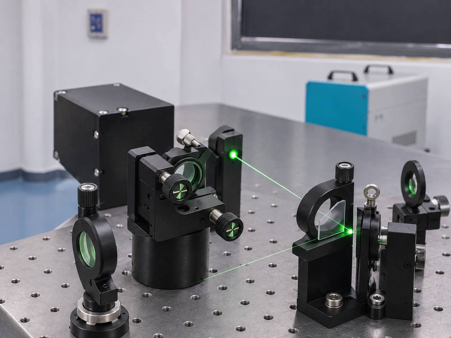
Need another ratio, range or angle? Ask us for a custom beamsplitter. Specify a custom filter
Three Kinds of Beamsplitter
Ratio Beamsplitters
Split a beam in a fixed ratio across the visible: 50:50, 60:40, 70:30, 80:20 and 90:10 at 45°, 400 to 700 nm.
Broadband Splitter
Transmits 80% on average from 550 to 1,100 nm, from green light into the near-infrared, for systems that need a small, steady pick-off across a wide band.
Wavelength Splitter
Separates two near-infrared lines 25 nm apart: 1,540 nm is reflected, 1,565 nm is transmitted at 90% or more. It works like a dichroic mirror. Dichroic mirrors
What to Check on a Beamsplitter Spec
Is the reflected side specified? Our ratio beamsplitters state tolerances for both transmission and reflection. Where only transmission is given, the reflected share is roughly the rest, minus a small loss in the coating and substrate.
Is your light polarized? At 45°, s- and p-polarized light split in different ratios, so a laser may not see the nominal ratio. Tell us the polarization, or ask for the ratio in yours.
Plates reflect from both faces, so a second, weaker beam appears beside the main reflection. Leave room for it in your layout, or ask about a back-side anti-reflection coating.
The comparison illustrates how 50:50 and 90:10 beamsplitters divide incident light between the transmitted and reflected paths.
What a ±5% Tolerance Means for Each Channel
Our ratio beamsplitters hold each channel to ±5 percentage points. On a 50:50 splitter, each side can be anywhere from 45 to 55%, so one channel can be up to about 1.2 times the other.
The weaker channel feels the tolerance most. On a 90:10 splitter, the reflected beam can be 5 to 15%, a factor of three between the lowest and highest. If your weak channel feeds a detector, calibrate it, or ask us for a tighter tolerance.
The measured ratio of each beamsplitter is available on request.
What to Specify
Have these ready when you ask for a quote. If you are unsure of some, tell us about your system and we will help fill them in:
- Split ratio, and its tolerance per channel
- Wavelength range for the ratio
- Angle of incidence (45° is standard)
- Polarization of your light
- Whether reflected beam ratio must be specified
- Substrate thickness, size and back-side coating
Standard Beamsplitters
| Model | Type | Specification | Range (nm) | AOI |
|---|---|---|---|---|
| 45D-FG400-650=50% | Ratio | TAvg = 50% | 400–650 | 45 ± 2° |
| FG550-1100=80% | Broadband | TAvg = 80% | 550–1,100 | 0 ± 2° |
| 45DFG-HR1540/HT1565 | Wavelength | TAvg = 90% at 1,565 nm; high reflection at 1,540 nm | 1,540 / 1,565 | 45 ± 2° |
Ratio Beamsplitter Series
| Ratio (T:R) | Transmission | Reflection | Range (nm) | AOI |
|---|---|---|---|---|
| 50:50 | 50% ± 5% | 50% ± 5% | 400–700 | 45° |
| 60:40 | 60% ± 5% | 40% ± 5% | 400–700 | 45° |
| 70:30 | 70% ± 5% | 30% ± 5% | 400–700 | 45° |
| 80:20 | 80% ± 5% | 20% ± 5% | 400–700 | 45° |
| 90:10 | 90% ± 5% | 10% ± 5% | 400–700 | 45° |
Beamsplitters in the first table are specified with a 3.5° cone half-angle. ± values are percentage points. Ask us for the curves.
Ratio Beamsplitter Series
| Ratio (T:R) | Transmission | Reflection | Range (nm) | AOI |
|---|---|---|---|---|
| 50:50 | 50% ± 5% | 50% ± 5% | 400–700 | 45° |
| 60:40 | 60% ± 5% | 40% ± 5% | 400–700 | 45° |
| 70:30 | 70% ± 5% | 30% ± 5% | 400–700 | 45° |
| 80:20 | 80% ± 5% | 20% ± 5% | 400–700 | 45° |
| 90:10 | 90% ± 5% | 10% ± 5% | 400–700 | 45° |
Beamsplitters in the first table are specified with a 3.5° cone half-angle. ± values are percentage points. Ask us for the curves.
Need a different split? Send us the ratio and its tolerance, the wavelength range, the angle of incidence, the polarization of your light and the size, and we will reply with a quote and a recommended design. Contact us